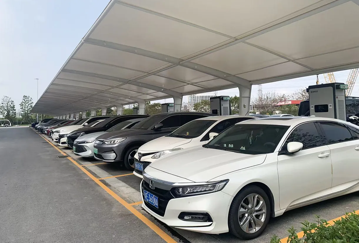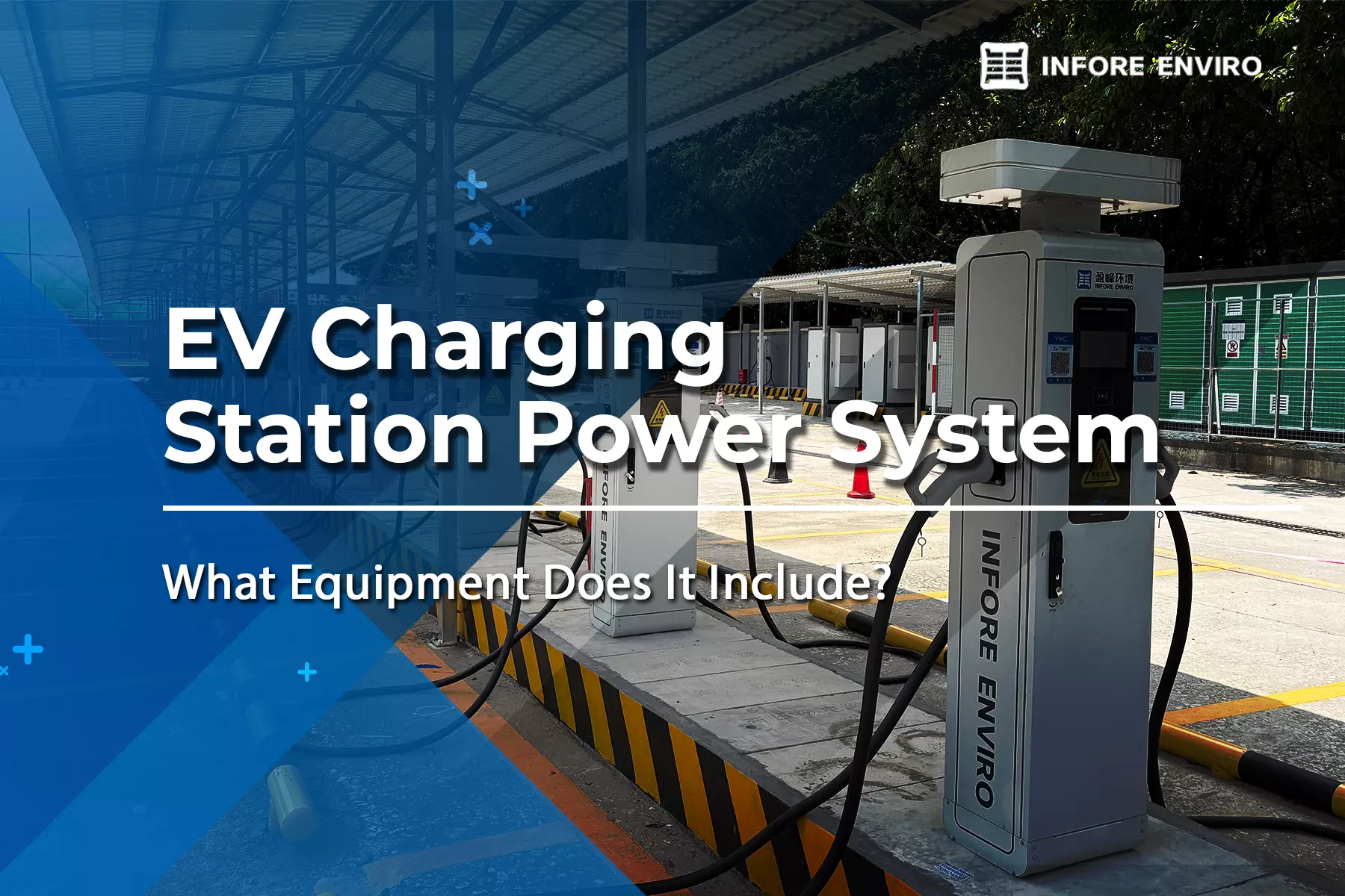
Deploying multi-unit DC fast charging infrastructure requires a coordinated strategy encompassing high-voltage electrical distribution, civil engineering, and network architecture. Unlike residential AC equipment, commercial DC fast charging installations—especially those featuring multi-gun 160 kW pedestals—place substantial instantaneous demands on local electrical grids and commercial site layouts.
Designing a scalable charging hub involves evaluating utility grid capacity, engineering concrete mounting pads, configuring dynamic power sharing, and implementing backend management protocols. Thorough upfront site planning prevents costly retrofits, optimizes installation budgets, and ensures seamless vehicle throughput for commercial fleets, retail hubs, and public charging plazas.
Executing a structured infrastructure plan provides property managers and fleet operators with a robust foundation for high-power electrification. The following framework outlines key technical considerations for deploying multi-unit CCS DC fast charger pedestals effectively.
Electrical Grid Demands and High-Power Substation Infrastructure
High-power DC fast charging bypasses the vehicle’s onboard AC converter, delivering direct current straight to the battery pack at high voltages. Operating a site with multiple 160 kW charging pedestals can require substantial electrical capacity and may involve service upgrades, dedicated transformers, or medium-voltage utility connections depending on the site’s existing infrastructure and utility requirements.
The INFORE ENVIRO 160kW dual-gun DC fast charger uses a three-phase AC400V±15% input, with an input current of ≤258A under the specified operating configuration. When multiple 160kW charging stations are deployed at the same site, aggregate power demand can become substantial, making early assessment of utility capacity and site electrical infrastructure important.
Key electrical infrastructure components for a multi-unit DC site include:
Utility Transformers and Service Equipment: Providing the appropriate electrical supply for the charger’s AC400V±15% input according to site conditions and local utility requirements.
Commercial Switchgear and Distribution Panels: Equipping panels with high-interrupting-capacity circuit breakers and integrated surge protection devices (SPDs).
Power Factor Correction and Harmonic Mitigation: Power Factor and Harmonic Management: The charger specifies a power factor of ≥99%, supporting efficient utilization of incoming AC power.
At INFORE ENVIRO, our high-power DC charging solutions incorporate high-efficiency power conversion modules designed to optimize energy conversion and minimize reactive power draw from the grid. Proper upstream electrical design ensures stable voltage delivery across all active charging pedestals during peak operational windows.
Civil Engineering, Concrete Foundation Pads, and Pedestal Layout
Installing robust charger pedestals requires significant civil works, including underground trenching, heavy-duty concrete pad pouring, and protective physical barriers. Designing the physical site layout must account for vehicle turning radiuses, parking stall dimensions, cable reach, and accessibility compliance.
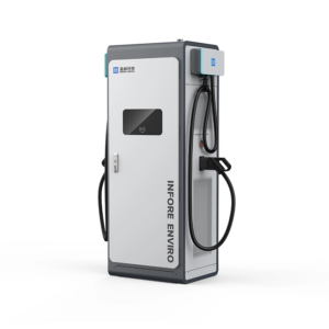
Concrete foundations should be designed around the charger’s physical dimensions, mounting requirements, cable entry points, and applicable site engineering standards. The INFORE ENVIRO unit measures 750mm × 600mm × 1950mm.
Essential civil planning requirements for multi-pedestal sites include:
Conduit and Trenching: Installing heavy-walled schedule 80 PVC or rigid metallic conduit (RMC) for 480V AC power feeds alongside separate isolated conduits for low-voltage Ethernet and data communication.
Structural Concrete Foundations: Pouring reinforced concrete pads with embedded anchor bolts and dedicated stub-up conduit entries aligned with station baseplates, with concrete strength specified per manufacturer requirements.
Physical Asset Protection: Installing heavy-duty steel safety bollards filled with concrete around each EV charger pedestal to guard against vehicle impacts.
Universal Accessibility: Designing stalls with adequate turning clearances, flush concrete transitions, and mounting screens or connectors within accessible reach heights.
Cable management should provide sufficient reach while keeping charging cables clear of vehicle paths and pedestrian areas. The charger is supplied with a 5m cable.
Hardware Integration: Dual-Gun CCS DC Fast Chargers and Dynamic Power Allocation
Selecting hardware with intelligent power allocation is essential to optimizing grid connection capacity while maximizing vehicle throughput. Multi-gun pedestals allow two vehicles to charge simultaneously from a single physical station footprint, significantly improving space efficiency
A dual-port CCS DC fast charger operating at 160 kW total output utilizes modular internal power rectifiers (such as eight 20 kW or four 40 kW modules) that dynamically route power to either connector based on vehicle demand:
Single-Vehicle Charge: Directs the full 160 kW output to one CCS connector for rapid high-power battery replenishment.
Key technical specifications for a 160 kW dual-gun CCS station include:
Input AC Voltage: 480V AC ±10%, 3-Phase, 3-Wire + PE
Output DC Voltage Range: 200V DC to 1000V DC (wide range supporting both 400V passenger EVs and 800V commercial platforms)
Maximum Output Current: 250A to 300A per connector with standard cooling, higher with liquid-cooled cables
Connector Configurations: Dual CCS2 or CCS1 connectors (with optional NACS or CHAdeMO integration based on market demand)
Peak System Efficiency: Equal to or greater than 95.5% using high-frequency power conversion modules
Implementing a CCS DC fast charger with a wide output voltage range (200V to 1000V DC) ensures native support for both standard 400V battery architectures and newer 800V high-voltage vehicle platforms without requiring external step-up hardware.
Hardware manufactured by INFORE ENVIRO features IP54/NEMA 3R industrial enclosures, flame-retardant internal construction, and intelligent forced-air or liquid cooling to maintain full 160 kW rated output even under high ambient temperature conditions.
Network Connectivity, OCPP Management, and Future Fleet Scalability
Operating a multi-unit pedestal infrastructure requires seamless backend software integration to manage access control, dynamic load balancing, automated billing, and real-time remote diagnostics.
Utilizing open standards such as OCPP 1.6J or OCPP 2.0.1 prevents vendor lock-in, enabling site hosts to pair hardware with their choice of charge point management software (CPMS).
Critical software and communication functions include:
Local Controller Dynamic Load Management (DLM): Automatically capping maximum concurrent site power draw at the master controller level to prevent tripping upstream switchgear or incurring utility demand charges.
Dual-Path Telemetry: Equipping each EV charger pedestal with redundant industrial 4G/5G cellular modems and dual Ethernet ports for uninterruptible cloud connectivity.
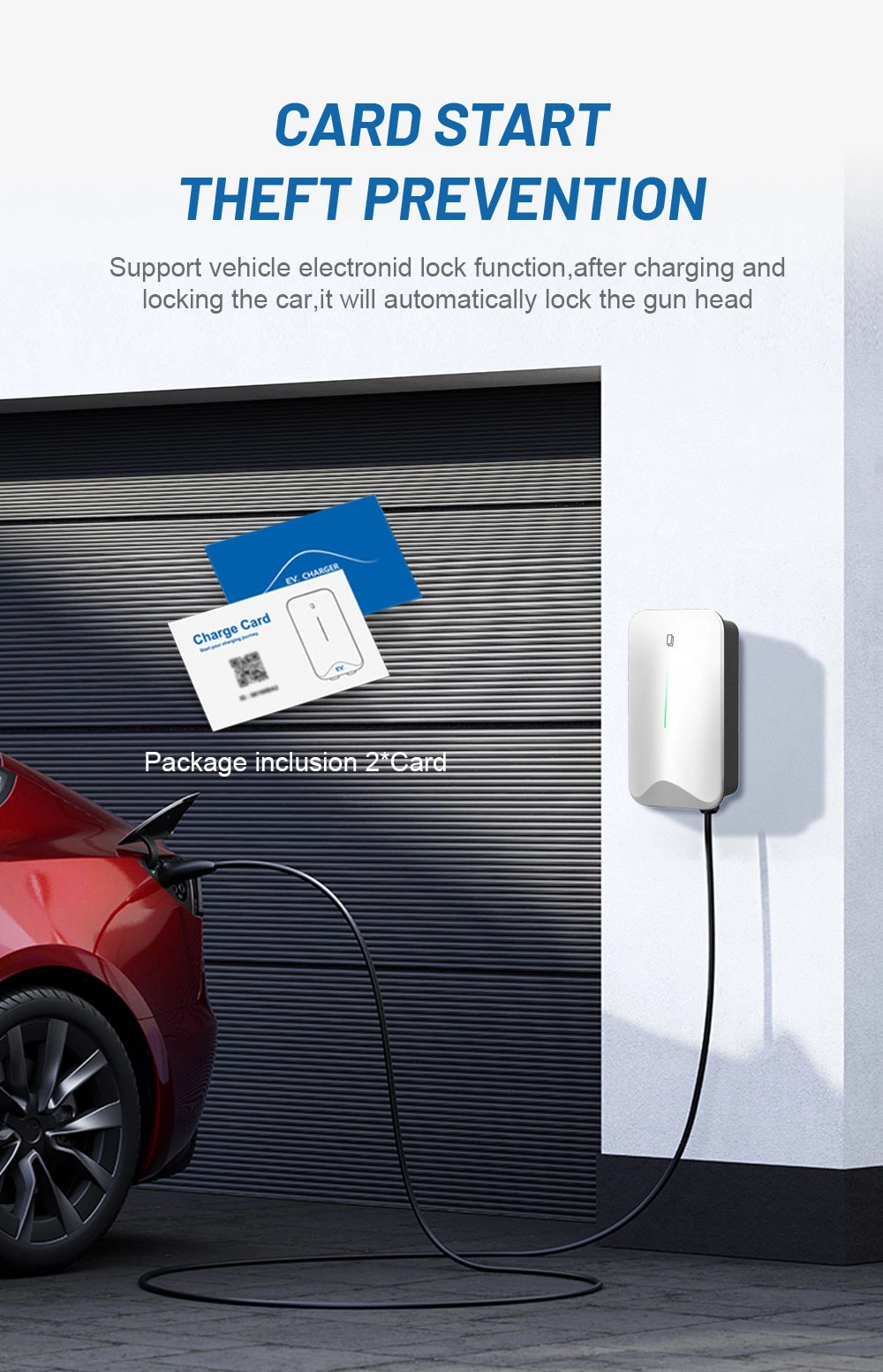
Payment and Authentication Options: Supporting RFID reader authorization, credit card POS terminals, Plug & Charge (ISO 15118), and mobile application access.
Designing the infrastructure for future expansion involves installing oversized conduit banks during initial civil trenching. Laying additional empty conduits during initial pad construction allows site operators to double their pedestal count in future phases without re-excavating concrete parking structures or repaving asphalt.
Combining robust civil preparation, high-efficiency power modules, dynamic power allocation, and OCPP software integration guarantees a long-term, scalable charging solution capable of supporting the next generation of electric mobility.
.webp)